All Model 9000’s are equipped with a USB 2.0 interface with provisions for an optional interface adapter that will support IEEE 1284 25 pin Parallel, IEEE 1284 36 pin Parallel, RS232 9 pin Serial, RS232 25 pin Serial, Powered USB or Ethernet 10/100-Base-T.
USB Interface
The USB interface is a Version 2.0 High or Full Speed implementation. The USB interface is standard on all printers and implemented through a Standard Series “B” Receptacle as defined in the USB Specification. The printer is self-powered and does not draw power from the standard type B USB interface cable.
The Standard USB Type B connector has the following pin functions:![]()
Table 5 Standard USB Pin definitions
Note: The + 5 power on the standard USB interface does not have enough power to run the printer.
Note: The Vbus signal may be used to place the printer in a low power mode, however, this requires the printer to be configured for Gree operation.
Powered USB Interface
The Model 9000 printer may be supplied with a powered USB interface as a factory installed option. The printer will be supplied with a standard 24V inline 8 pin powered USB connector. See the Powered USB web site http://www.poweredusb.org for the Powered USB standards. Matching cables are available from Transact or from CyberData. See http://www.cyberdata.net/products/cables/pusbcables/index.html for a list of cables available from CyberData.
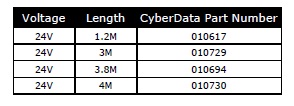
Table 6 CyberData Powered USB 24V to 1×8 Cables
The Powered USB inline 8 connector has the following pin functions:
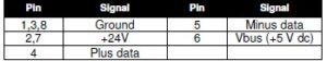
Table 7 Powered USB Pin definitions
Note: Printers with the powered USB interface are supplied with an internal power supply. No other interface adapter may be installed in these printers.
Parallel Interface
Your printer features two parallel interface options:
- An IEEE 1284-A 25-pin, D-shell connector, with pin-outs that interface to a standard IBM PC parallel printer interface with a one-to-one cable.
- An IEEE 1284-B, which is a standard Centronics 36-pin connector.
Both interface cards provide a dual cash drawer interface. The following table lists interface signals and corresponding pins
| 25-pin Connector | 36-pin Connector | Signal | Description | Direction |
| Pin 1 | Pin 1 | STROBE | Clock data to printer | Host to Printer |
| Pins 2-9 | Pins 2-9 | D0 – D7 | Data | Host to Printer |
| Pin 10 | Pin 10 | ACK | Printer accepted data | Printer to Host |
| Pin 11 | Pin 11 | BUSY | Printer busy | Printer to Host |
| Pin 12 | Pin 12 | PE | Paper Out/Status | Printer to Host |
| Pin 13 | Pin 13 | SLCT | Printer selected | Printer to Host |
| Pin 14 | Pin 14 | AUTOFD | Autofeed paper | Host to Printer |
| Pin 15 | Pin 32 | FAULT | Printer error | Printer to Host |
| Pin 16 | Pin 31 | INIT | Initialize printer | Host to Printer |
| Pin 17 | Pin 36 | SLIN | Select printer | Host to Printer |
| Pin 17 | FG | Frame ground | Printer to Host | |
| – | Pin 18 | +5V | Peripheral logic high | Printer to Host |
| Pins 18-25 | Pins 16, 19-30 | GND | Ground |
Table 8 Parallel Interface Pin definitions
RS-232 Serial Interface
Serial Port Features
The serial port features are as follows:
Baud Rates 300, 600, 1200, 2400, 4800, 9600, 19.2K, 38.4K, and 57.6K
Bit Patterns 8-bit no parity; 8-bit odd; 8-bit even; 7-bit no parity; 7-bit odd; 7-bit even
Flow Control DTR and XON/XOFF
| 9-pin | 25-pin | Signal | Description |
| Pin 1 | Pin 8 | Not Connected | |
| Pin 2 | Pin 3 | RX | Receive Data |
| Pin 3 | Pin 2 | TX | Transmit Data |
| Pin 4 | Pin 20 | DTR | Data Terminal Ready |
| Pin 5 | Pin 7 | GND | Signal Ground |
| Pin 6 | Pin 6 | DSR | Data Set Ready |
| Pin 7 | Pin 4 | RTS | Request to Send |
| Pin 8 | Pin 5 | CTS | Clear to Send |
| Pin 9 | Pin 11 | Not Connected |
Table 9 Serial Interface Pin definitions
Because both the host and printer are DTE’s (Data Terminal Equipment), they use the same serial port pin-outs. If the cable that is used to connect the host to the printer is a pin-to-pin inter-connect, it will not work. Therefore, a null modem or turn-around cable must be used to interconnect the host and the printer.
Display Pass Through
The display pass through feature allows a pole display to be interconnected with the printer. The printer is connected to a host system with a special serial cable. The host sends serial data to the printer and the printer sends serial data to the pole display. The printer does not provide power to the display. During normal printer operation, no data is passed to the display. In pass through mode, all received data is passed on to the display.
Ethernet 10/100-Base-T adapter
An IP addressable 10-Base-T Ethernet adapter is available for the Model 9000 printer. A users manual for this adapter is available from transact. The user’s manual part number is100-10938.
The adapter provides for web page configuration and supports bi-directional RAW and Telnet interfaces. All protocols are implemented to the extent necessary to support printing from Windows™ platforms; specific protocols supported include the following:
- TCP/IP Port 9100 (RAW data)
- Line Printer Daemon Protocol (LPR)
- Hypertext Transfer Protocol (for configuration)
- UDP Port 9110 for real time status
- DHCP or IPv4 address assignment.
- SNMP RFC1213 for printer and network management
General Ethernet Definitions
The Internet Protocol (IP) is the principal communications protocol used for relaying packets of information across an network. The IP is responsible for routing packets across network boundaries and is the primary protocol that establishes the Internet. IP defines addressing methods and structures for information encapsulation.
The Transmission Control Protocol (TCP) is one of the core protocols of the Internet Protocol Suite. TCP is one of the two original components of the suite, complementing the Internet Protocol (IP), and therefore the entire suite is commonly referred to as TCP/IP. TCP provides the service of exchanging data directly between two network hosts, whereas IP handles addressing and routing message across one or more networks. In particular, TCP provides reliable, ordered delivery of a stream of bytes from a program on one computer to another program on another computer. Other applications, which do not require reliable data stream service, may use the User Datagram Protocol (UDP) which provides a datagram service that emphasizes reduced latency over reliability.
The Model 9000 uses TCP/IP port 9100 to connect the host system to the printer and then use the native printer protocol (sometimes referred to as Raw Data) to communicate with the printer. The host system opens a TCP/IP connection to the printer and by sending data to the printer on port 9100 and listening to returned information on port 9100 and send commands and data to the printer and receive status back.
The User Datagram Protocol (UDP) is one of the core members of the Internet Protocol Suite. With UDP a computer applications can send and receive messages to and from other computers or devices using an Internet Protocol (IP) network without requiring prior communications to set up special transmission channels or data paths.
UDP uses a simple transmission model without implicit hand-shaking dialogues for providing reliability, ordering, or data integrity. Thus, UDP provides an unreliable service and information may arrive out of order, appear duplicated, or go missing without notice. UDP assumes that error checking and correction is either not necessary or performed in the application, avoiding the overhead of such processing at the network interface level. Time-sensitive applications often use UDP because dropping packets is preferable to waiting for delayed packets, which may not be an option in a real-time system.
UDP’s stateless nature is also useful for servers answering small queries from huge numbers of clients (Model 9000 printers). Unlike TCP, UDP is compatible with packet broadcast (sending to all on local network) and multicasting (send to all subscribers).
Common network applications that use UDP include: the Domain Name System (DNS), streaming media applications such as IPTV, Voice over IP (VoIP), File Transfer UDP is used by the Model 9000 to support real time status monitoring.
The Model 9000 Ethernet Adapter supports the UDP protocol to handle printer status without the TCP-IP interface being open. When Activated the Ethernet Adapter will report printer status to the specified host without the TCP/IP link being open. The Ethernet Adapter uses IP port 9110 to report status and control the UDP interface. The Ethernet Adapter II supports 6 commands and 10 reports. Each command has an associated response report plus there are 4 additional printer status reports. See the Ethernet adapters user’s manual (100-10938) for more information.
The default iTherm Ethernet Adapter’s UDP IP port is 9110 however, this is configurable. At this time the UDP server in the iTherm Ethernet Adapter is similar to the UPnP service in that it does not require an exact match for source or destination IP addresses. It will respond to IP broadcasts, local subnet broadcasts, and the Ethernet Adapter’s specific IP address. In addition the source port need not match the Ethernet adapters, provided that it is directed to the Ethernet Adapters UDP IP port.
The Hypertext Transfer Protocol (HTTP) is a networking protocol for distributed, collaborative, hypermedia information system. HTTP is the foundation of data communication for the World Wide Web.
The Model 9000 printer used HTTP to provice the ability to configure the Ethernnet interface adapter using any standard web browser.
The Dynamic Host Configuration Protocol (DHCP) is an auto configuration protocol used on IP networks. Computers that are connected to IP networks must be configured before they can communicate with other computers on the network. DHCP allows a computer to be configured automatically, eliminating the need for intervention by a network administrator. It also provides a central database for keeping track of computers that have been connected to the network. This prevents two computers from accidentally being configured with the same IP address.
In the absence of DHCP, the printer may be manually configured with an IP address.
A subset of the Simple Network Management Protocol (SNMP) printer MIB (RFC1213) is supported by the Model 9000 that will allow limited printer monitoring.
Cash Drawer
Interface Description
The Model 9000 Printer supports a single cash drawer with status. The driver in the printer is capable of supplying 24 V DC at up to 1.5 amps for up to 250 milliseconds. The Model 9000 Printer defines cash drawer closed as switch open. If the drawer is disconnected, it will be viewed by the printer as closed. Since the printer does not act on the cash drawer status, the application can interpret cash drawer status any way it wants.
Driver connector type (standard) Single RJ12 connectors with 24V sink drivers
Driver voltage 24 volts (Refer to power supply specification).
Driver current 1 amp maximum with current limit
Pulse duration 250 msec. maximum
Drawer status Open/close drawer status provided to printer
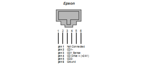
Figure 3 Cash Drawer Pin Definitions
| Pin Number | Epson | |
| Signal Name | Direction | |
| 1 | Drawer kick-out drive signal 2 | Output Sink Drive |
| 2 | Drawer open/close signal | Input |
| 3 | Signal ground | |
| 4 | +24V DC | |
| 5 | Drawer kick-out drive signal 1 | Output Sink Drive |
| 6 | Frame Ground |